


 400-800-6892


 CN
CN
![]()
![]()
CN
![]()
![]()
400-800-6892Release time:2025-09-26 Click count:0
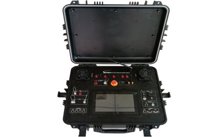
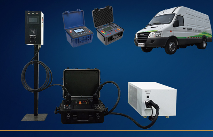
Skonda portable AC charging station testing and metering comprehensive instrument PEV7001, with interoperability testing and metering verification function testing. Mainly used for interoperability function verification, charging timing condition detection, and metrological verification of newly installed AC charging piles, repaired AC charging piles, and upgraded AC charging piles. The comprehensive instrument has the characteristics of high accuracy, small size, light weight, and easy portability, which can meet the measurement and performance testing needs of various occasions such as laboratories and on-site. The comprehensive instrument has a measurement module that meets the metrological verification regulations of JJG 1148-2018 Electric Vehicle AC Charging Station. It can verify voltage error, current error, power error, working error, indication error, payment amount error, and clock indication error. The built-in software function module implements the testing items of "GB/T 34657.1-2017 Electric Vehicle Conductive Charging Interoperability Test Specification Part 1 Power Supply Equipment" and comes with two 63A standard charging gun sockets, with pin definitions meeting the requirements specified in GB/T 20234.2-2015.

Features:
When measuring, the load is allowed to be connected to the actual vehicle or any simulated load
It has the function of detecting environmental temperature, calculating the error caused by temperature based on the actual working scene temperature, and determining the measurement results.
Equipped with GPS timing function, it can perform Beijing time timing error testing on the charger.
Equipped with a charging timing test interface, it can be connected to pile end signals such as emergency stop switch actions to meet interoperability testing standards.
It has a 16 channel timing synchronization measurement function, which can meet the timing testing related to interoperability testing, such as T1, T1 ', T2, T2', T3, T3 ', T3' ', T2-T2' time, etc.
Built in vehicle end R2 resistor, R3 resistor simulation equivalent resistance simulation function, R2 resistor adjustment range of 500 Ω~4000 Ω, resistance value continuously adjustable online, adjustment fineness of 1 Ω, R3 equivalent resistance nominal value of 1400 Ω~8000 Ω, resistance value continuously adjustable online, adjustment fineness of 1 Ω. Each contact is equipped with an on-off switch, which can simulate the on-off state of the contact.
It has the function of measuring the voltage, current, and CP signal of AC charging stations.
Built in national standard testing projects, automated program testing and report generation to facilitate changes and upgrades to national standard items.
The comprehensive instrument has the function of generating test report templates, which can generate test report formats according to the customer's layout format. The report formats can be TXT, EXECL, XLC, WORD.
The test report supports multiple data export methods: exporting directly from a USB flash drive, exporting through a computer connected to a device via WIFI, and uploading to the enterprise's database platform via 4G.
National standard testing items, modular testing functions, network data interfaces, supporting cross platform calling.
The testing module of the comprehensive instrument software platform has structured input and output standard data, which is easy to parse and call.
The comprehensive instrument has a 10 inch high-definition LCD touch screen, which is convenient for users to touch and operate.
4.1. Basic functional items
4.1.1. Vehicle interface simulation
| NO. | Test project | ||
| 1 | Measurement of charging station parameters | 1. Type of charging station 3. Charging pile current specification | 2. Connection method of charging station |
| 2 | Vehicle interface simulation | 1. Switch S2 state simulation 3. Vehicle interface PE pin status 5. Control and guide circuit R2 resistance simulation | 2. Vehicle interface CP pin status simulation 4. Control and guide circuit R3 resistance simulation |
| 3 | Charging parameter measurement | 1. A-phase charging voltage 3. B-phase charging voltage 5. C-phase charging voltage 7. CP signal high value 9. CP signal frequency 11. Charging status | 2. A-phase charging current 4. B-phase charging current 6. C-phase charging current 8. CP signal low value 10. CP signal duty cycle |
4.1.2. Interoperability specification testing
It can meet all the testing items specified in the national standard GB/T 34657.1-2017 Test Specification for Interoperability of Conductive Charging of Electric Vehicles Part 1 Power Supply Equipment, as shown in the following table:
| Serial number | Project Name | Corresponding chapters | PEV7001 |
| A1.1001/I1.1001 | Connection confirmation test | 6.4.2.1 | √ |
| A1.3001/I1.3001 | Charging readiness test | 6.4.2.2 | √ |
| A1.4001/I1.4001 | Start up and charging phase testing | 6.4.2.3 | √ |
| A1.5001/I1.5001 | Normal charging end test | 6.4.2.4 | √ |
| A1.6001/I1.6001 | Charging connection control timing test | 6.4.3 | √ |
| A1.3501/I1.3501 | CC disconnection test | 6.4.4.2 | √ |
| A1.3502/I1.3502 | CP disconnection test | 6.4.4.2 | √ |
| A1.4501/I1.4501 | CP grounding test | 6.4.4.3 | √ |
| A1.4502/I1.4502 | Continuity loss test of protective grounding conductor | 6.4.4.4 | √ |
| A1.4503/I1.4503 | Output overcurrent test* | 6.4.4.5 | √ |
| A1.4504/I1.4504 | Disconnect switch S2 for testing | 6.4.4.6 | √ |
| A1.6002/I1.6002 | CP circuit voltage limit test | 6.4.5.1 | √ |
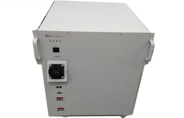
*The testing project requires an external load module PACR-380/220-27/10 for automatic control.
4.1.3. Measurement of AC charging stations
Can meet all test items specified in the national standard GB/T 34658-2017 Communication Protocol Consistency Test between Off board Conductive Chargers and Battery Management Systems for Electric Vehicles; It can meet the metrological verification regulations of JJG 1149-2018 Electric Vehicle Off board Charging Machine, as shown in the following table:
| Inspection Items | Initial verification | Subsequent verification | In use verification |
| Visual inspection | + | + | + |
| Insulation resistance test* | + | + | - |
| working error | + | + | - |
| indication error | + | + | + |
| Payment amount error | + | + | + |
| Clock indication error | + | + | - |
*The insulation resistance test requires additional high-voltage equipment to be configured, and the test data is manually input.
4.2. Technical specifications and parameters
4.2.1. Measurement specifications
| measurement | ||
| AC voltage | range | 300V |
| scope | 300V | |
| accuracy | ±0.1%+0.1%F.S. | |
| resolution | 0.01%F.S. | |
| alternating current | current range | 75A |
| scope | 75A | |
| accuracy | ±0.1%+0.1%F.S. | |
| resolution | 0.01%F.S. | |
| CP signal | measurement range | -15V~+15V |
| Measurement accuracy | ±15mV | |
| Measurement resolution | 7.5mV | |
| time | accuracy | ±0.1ms(T ≤ 1000ms) ±1ms(1000ms<T) |
| resolution | 0.1us | |
| Timing function | ||
| Time series measurement | number of channels | 16 |
| scope | 0.1s-300s | |
| precision | ±1ms(≤1000ms);±(0.1%±10ms)(>1000ms) | |
| resolution | 100us | |
| Timing point | Voltage, current, CP VDC、CP PWM、ACON、CC SYNC、EPO、S2OPEN、S2CLOSE | |
| simulation | ||
| R2 resistor | scope | 500-4000Ω |
| resolution | 1Ω | |
| R3 resistor | scope | 1400-8000Ω |
| resolution | 1Ω | |
4.2.2. Measurement parameters
| AC voltage | range | 150V、300V |
| scope | 30~300V | |
| accuracy | ±0.05%RD (30V ≤ V ≤ 300V), Temperature coefficient: ±(5ppm*RD+5ppm*RG)/℃ | |
| resolution | 0.01%RG | |
| alternating current | current range | 60A |
| scope | (0~110%)RG | |
| accuracy | ±0.05%RD (3A ≤ I ≤ 60A), Temperature coefficient: ±(5ppm*RD+5ppm*RG)/℃) | |
| resolution | 0.01%RG | |
| power | accuracy | ±0.05%RD (30V ≤ U ≤ 300V,3A ≤ I ≤ 60A) |
| power factor | scope | -1.0~0~+1.0 |
| accuracy | ±0.0005 (30V ≤ U ≤ 300V,3A ≤ I ≤ 60A) | |
| resolution | 0.0001 | |
| frequency | effective range | 40Hz~70Hz |
| accuracy | ±0.01Hz | |
| resolution | 0.001 Hz | |
| phase | scope | 0.000°~359.999° |
| accuracy | ±0.02°(30V≤U≤300V, 3A≤I≤60A) | |
| resolution | 0.001° | |
| electric energy | accuracy | ±0.05%RD (30V ≤ U ≤ 300V,3A ≤ I ≤ 60A) |
| Electric pulse output | Output constant | 1-2000000000 |
| maximum frequency | 160kHz | |
| pulse type | TTL/CMOS compatible level output | |
| Electric energy pulse input | pulse constant | 1-2000000000 |
| Range of turns | 1-999999999 | |
| Maximum received pulse frequency | 50kHz | |
| GPS timing | Precision | ±1us |
| Clock | Accuracy | ±0.1ppm |
| Temperature measurement | Accuracy | ±0.3℃ |
| Resolution | 0.1℃ | |
| Humidity measurement | Accuracy | ±4% |
| Resolution | 0.01 |
4.2.3. System Parameters
| Power supply | Input voltage range | 85-264Vac @47-63Hz |
| Maximum Power Consumption | 60VA | |
| Peripheral interface | USB | 2 |
| RS232 | 1 | |
| LAN | 1 | |
| WIFI | 1 | |
| 4G network interface | 1 | |
| Human-computer interaction | 10-inch touch screen | |
| Ambient temperature | Operating Temperature | -30℃~55℃ |
| Operating Humidity | ≤ 95% non condensing | |
| Storage temperature | -40℃~70℃ | |
| warm-up time | 5 minutes | |
| Dimensions & Weight | Dimensions (length * width * height) | 613*488*266mm |
| weight | 25kg | |
| weight | 29kg |
2025-09-26
2025-09-26

2025-04-22
2025-09-26
2025-09-26


 Service Hotline
 Email
Email URL
URL Address
 WeChat Channels
 Tiktok account
 WeChat Official Account
 WeChat Service Account


